Doing so may render the system inoperable, generating a blue screen. The FCoE Stack and base driver need to be matched. The FCoE stack may get out of sync with X520, if the X520 base drive is updated via Windows Update.
Upgrading from Software Release 15.4
Validation and Storage Certification
New Windows Server 2008 Installation
Intel® Ethernet FCoE Configuration Using Intel® PROSet for Windows* Device Manager
Upgrades for Software Release 16.2 or later are supported when Intel® Ethernet FCoE Boot is enabled or the Windows paging file is on an FCoE target. Upgrading an FCoE-booted system can only be done via the Intel® PROSet for Windows* Device Manager installer. A reboot is required to complete the upgrade.
| Warning: Do not update X520 base driver via the
Windows Update method Doing so may render the system inoperable, generating a blue screen. The FCoE Stack and base driver need to be matched. The FCoE stack may get out of sync with X520, if the X520 base drive is updated via Windows Update. |
The Windows FCoE stack has recently changed the way it creates the initiator WWPN. The first two bytes of the WWPN previously contained a 2 followed by the FCoE fabric VLAN ID. The VLAN ID is no longer added to the WWPN and the first two bytes will now always be 20:00. After upgrading from Release 15.4, you will need to zone the new WWPN for each initiator port.
The software components for Intel® Ethernet FCoE are comprised of two major components: the Intel® Ethernet base driver and the Intel® Ethernet FCoE Driver. They are developed and validated as an ordered pair. Users are strongly encouraged to avoid scenarios, either through upgrades or Windows update, where the Intel® Ethernet driver version is not the version released with the corresponding Intel® Ethernet FCoE driver. Listed below is a table with the released versions and the associated base driver and the Intel® Ethernet FCoE Driver.
 Notes:
 |
Individually upgrading/downgrading the Intel® Ethernet FCoE driver will not work and may even cause a blue screen; the entire FCoE package must be the same version. Upgrade the entire FCoE package using Intel® Network Connections only. If you uninstalled the Intel® Ethernet Virtual Storage Miniport Driver for FCoE component, just find the same version that you uninstalled and re-install it; or uninstall and then re-install the entire FCoE package. |
|
Version |
Qualified |
NDIS Miniport Driver |
Intel® Ethernet FCoE Drivers |
| 15.4 | No | 2.5.52.0 | 1.0.2.0 |
| 15.4.1 | Yes | 2.5.52.0 | 1.0.2.1 |
| 15.4.2 | Netapp | 2.5.52.0 | 1.2.6.0 |
| 15.4.3 | EMC | 2.5.52.0 | 1.2.8.0 |
| 15.8 | No | 2.6.121.0 | 1.3.23.0 |
| 16.0 | No | 2.7.28.0 | 1.4.6.0 |
| 16.2 | EMC, Netapp | 2.8.32.0 | 1.5.9.0 |
| 16.4 | No | 2.9.66.0 | 1.6.5.0 |
Intel and the storage vendors spend considerable effort ensuring that their respective products operate with each other as expected for every version that we release. However, given the sheer number of releases and each respective organizations' differing schedules, users are strongly encouraged to use their storage vendor's support matrix to ensure that the versions that they are deploying for the Intel® Ethernet Protocol Driver, the switch and storage vendor have been tested as an integrated set.
From the Intel CD: Click the FCoE/DCB checkbox to install Intel® Ethernet FCoE Protocol Driver and DCB. The MSI Installer installs all FCoE and DCB components including Base Driver.
|
|
FCoE is supported on 82599 and X540-based Intel® Network Connections. We recommend installing using the latest Storage Qualified Image. For current drivers and documentation, visit the Customer Support site. |
The following Microsoft hotfixes have been found to be needed for specific use cases:
All Windows Server 2008 (R1 and R2)
Multipath I/O (MPIO)
Windows 2008 R1 SP2
Windows 2008 R2
Windows 2008 R2 SP1
Configuring MPIO Timers: <http://technet.microsoft.com/en-us/library/ee619749(WS.10).aspx> contains additional information about these registry settings.
Set the PathRecoveryInterval value to 60
iSCSI Over DCB - QOS binding
Windows 2008 R1 SP2
Many FCoE functions can also be configured or revised using Intel PROSet for Windows Device Manager, accessed from the FCoE Properties button within the Data Center tab. You can use Intel PROSet to perform the following tasks:
Click here for instructions on installing and using Intel PROSet for Windows Device Manager.
 Note:
Note: |
PROSetCL.EXE is used for DCB/FCoE configuration on Microsoft* Windows* Server 2008 Core and Microsoft* Windows* Server 2008 R2 Core operating systems. |
|
|
From the Boot Options Tab, the user will see the Flash Information Button. Clicking on the Flash Information Button will open the Flash Information Dialog. From the Flash Information Dialog, clicking on the Update Flash button allows Intel® iSCSI Remote Boot, Intel® Boot
Agent (IBA), Intel® Ethernet FCoE Boot, EFI, and CLP to be written. The
update operation writes a new image to the adapter's Flash and
modifies the EEPROM, which may temporarily disable the operation
of the Windows*
network device driver. You might need to reboot the computer
following this operation.
You cannot update the flash image of a LOM; this button will be disabled. |
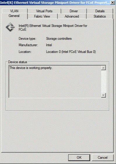
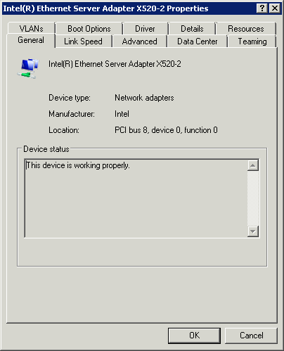
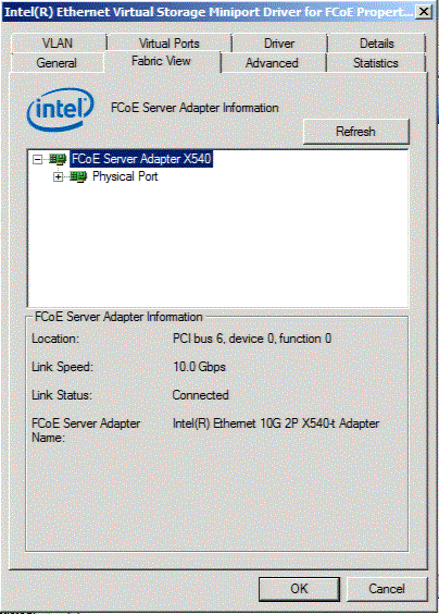
FabricView in connected mode
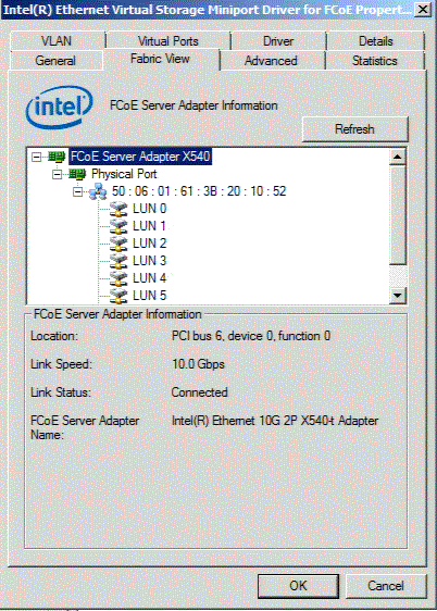
FabricView after completion of zoning and LUN masking
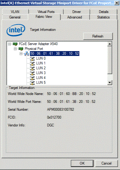
Fabric Mode with Target Selected
Selecting the target displays target information including: World Wide Node Name (WWNN), World Wide Port Name (WWPN), Serial Number, Fabric ID (FCID) and manufacturer name.
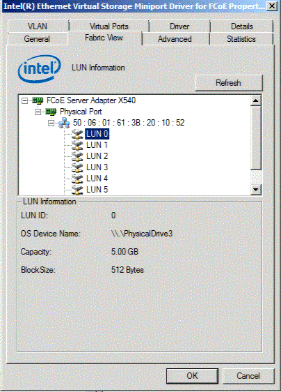
Fabric Mode with LUN Selected. Selecting a specific LUN from the list will display LUN information.
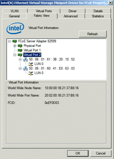
Fabric View Tab with Virtual Ports
The Fabric View Tab displays information about Virtual Ports, Targets and LUNs connected to the host adapter. It also displays detailed information about the host, the target and LUNs, e.g., the host name, target name, LUN capacity, FCID, etc.
| Location | |
| PortWWN | PortWWN is an unique 8-byte address of the port within the Fibre Channel network or domain. |
| NodeWWN | NodeWWN is a unique, 8-byte address of the node within the Fibre Channel network or domain. |
| FcId | FcId is a 3-byte unique identifier that addresses a port within the fabric domain, usually assigned by the fabric. |
| Link Status |
Connected Degraded (Class of Service not negotiated) Degraded (App mode disabled locally) Degraded (App mode disabled on peer) Connected (Class of Service unknown) Degraded (Data Center Bridging is disabled) Degraded (Data Center Bridging service not installed or started) Degraded (No Class Of Service negotiated) Degraded (PFC and APP setting mismatch) Degraded (Priority Flow Control is disabled) Degraded (Priority Flow Control not negotiated) Connected (Priority Flow Control state unknown) Not Connected (Fibre Channel link down) Not Connected |
| Refresh button |
Scans for any new targets/LUNs added since the
Fabric View property sheet was opened.
|
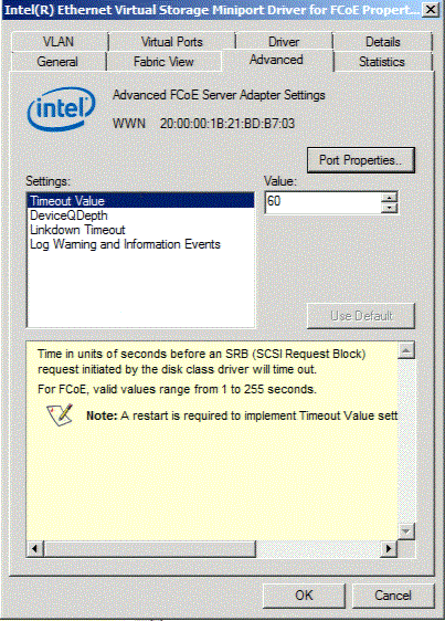
The Advanced Tab displays information about all the settings configurable from the host. These include Timeout Value, Linkdown Timeout, DeviceQDepth.
| Port Properties | This button opens Intel® Proset for Windows* Device Manager for the selected adapter. | ||
| SETTINGS: | |||
| Timeout Value |
Time in units of seconds before an SRB request initiated by the disk
class driver will time out.
|
||
| DeviceQDepth | Changes the Drive I/O Queue Depth value. This change may affect driver performance. Values for this setting are between 1-252 in increments of 1. Default value: 32. | ||
| Linkdown Timeout | Changes the time limit that I/O will be held on a link down. This value supersedes the Timeout Value setting. The values are 2, 5, 10, 15, 20, 30, 60, 90, and 120. Default value: 20 | ||
| Log Warning and Information Events | Allows user to enable/disable warnings in the event log if it is detected that the FCoE Interface Version returned from the base driver does not match the version that was validated. |
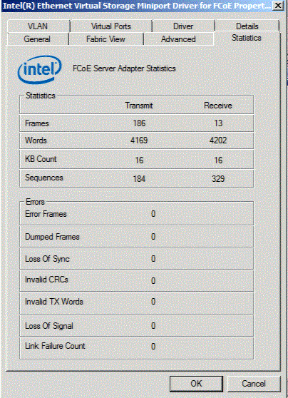
The Statistics Tab displays FCoE Server Adapter Statistics and errors since the initialization of the FCoE stack.
| Tx Frames | Number of total Transmitted Fibre Channel frames across all protocols and classes. |
| Rx Frames | Number of total Received Fibre Channel frames across all protocols and classes. |
| Tx Words | Number of total Transmitted Fibre Channel words across all protocols and classes. |
| Rx Words | Number of total Received Fibre Channel words across all protocols and classes. |
| LIP Count | Number of LIP events that have occurred on a arbitrated loop. |
| NOS Count | Number of NOS events that have occurred on the switched Fabric. |
| Error Frames | Number of frames that have been received in error. |
| Dumped Frames | Number of frames that were lost due to a lack of host buffers available. |
| Loss of Sync | Number of times loss of sync has occurred. |
| Loss of Signal | Number of times loss of signal has occurred. |
| Invalid Tx Word | Number of invalid transmitted words. |
| Invalid CRC | Number of frames received with invalid CRC |
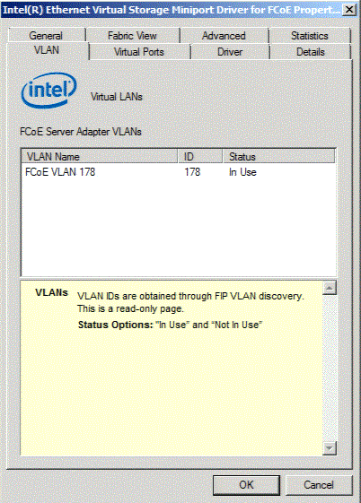
VLAN IDs are obtained through FIP VLAN discovery. This is a read-only page.
| Status Options | "In Use" and "Not In Use" |
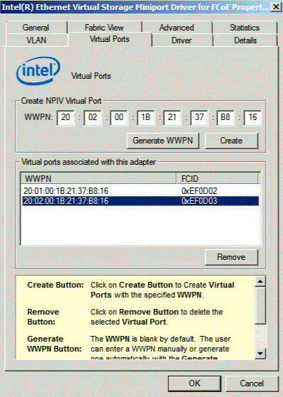
| Create Button | Creates Virtual Ports with the specified WWPN. |
| Remove Button | Deletes the selected Virtual Port. |
| Generate Button | The WWPN is blank by default. The user can enter a WWPN manually or generate one automatically with the Generate Button. |
A list of the Virtual Ports associated with the HBA has a column for the WWPN and FCID for each Virtual Port. Not Connected is displayed in the FCID column if it is not logged in to a target.

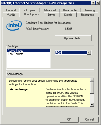
From the Boot Options tab you can obtain Target information and Update the Flash.
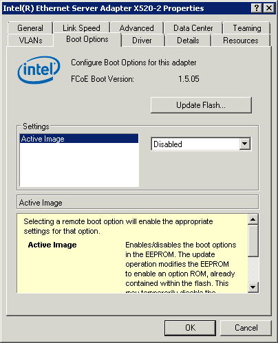
Enabling FCoE boot will allow user to boot from FCOE LUN.
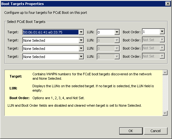
Selecting Boot Target in the above Window will allow user to select FCoE LUNs and their respective boot order.
| SETTINGS: | |||||||
| Active Image | Enables/disables the boot options in the EEPROM. The update operation modifies the EEPROM to enable an option ROM, already contained within the flash. This may temporarily disable the operation of the Windows* network device driver. You might need to reboot the computer following this operation. | ||||||
| Boot Targets | The server side system in an FCoE SAN configuration. The FCoE Boot Target system hosts the FCoE target drives which are accessed by an FCoE Boot initiator. | ||||||
| Update Flash Button | Click on the Flash Information Button to open the Flash Information Dialog. From the Flash Information Dialog clicking on the Update Flash button allows
Intel® Ethernet FCoE Boot, Intel® iSCSI Boot, Intel® Boot
Agent (IBA), EFI, and CLP to be written. The
update operation writes a new image to the adapter's Flash and
modifies the EEPROM, which may temporarily disable the operation
of the Windows* network device driver. You might need to reboot the computer
following this operation.
|
||||||
| Properties Button | Click on Properties button with
Boot Targets selected to
launch Target Properties Dialog.
|
||||||
| Target Properties Dialog |
LUN and Boot Order fields are disabled and cleared when target is set to None Selected.
Intel® Ethernet FCoE Boot cannot be enabled on an adapter that has a VLAN or is in a team.
|
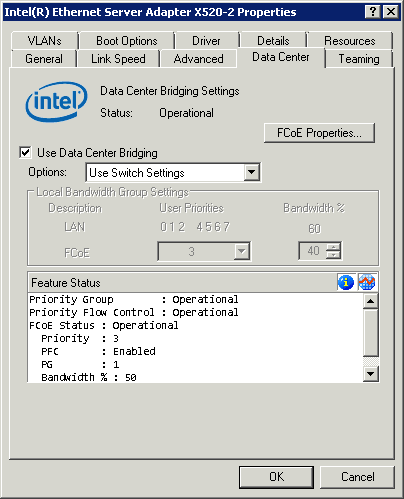
User must enable Use Data Center Bridging to be able to use Intel® Ethernet FCoE.
Changing FCoE priority allows the user to choose a different priority class for FCoE traffic on the converged Ethernet network. Adjusting Bandwidth percentage ensures FCoE traffic is allocated to specified minimum guaranteed bandwidth. All other traffic classes will share the remaining bandwidth. Bandwidth allocation rules are enforced when maximum available bandwidth is being utilized.
Use Switch Settings
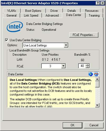
Use local settings
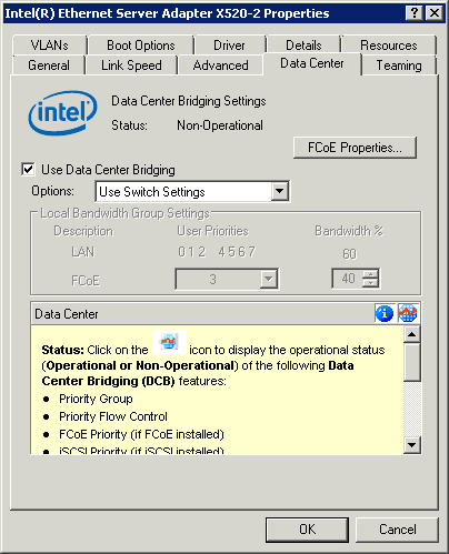
From the Data Center tab you can, among other things: view operational status, select FCoE settings, and enable/disable Data Center Bridging (DCB).
Non operational status: If the Status indicator shows that DCB is non-operational, there may be a number of possible reasons.
A non-operational status is most likely to occur when Use Switch Settings is selected or Using Advanced Settings is active. This is generally a result of one or more of the DCB features not getting successfully exchanged with the switch. Possible problems include:
When Use Local Settings is selected, the status should always be operational.
 Note:
Note: |
In most circumstances, we recommend selecting Use Switch Settings, rather than Use Local Settings. |
 Note:
Note: |
Options on the Data Center
tab are grayed out: You cannot disable DCB or modify any DCB settings while the system is booted from an FCoE drive or if the system paging file is on an FCoE drive. |
Last modified on 9/09/11 10:34a Revision