
Socket Queue to CPU Allocation
The phrase “Receive Side Scaling” (RSS) refers to the idea that all receive data processing is shared (scaled) across multiple processors or processor cores. Without RSS all receive data processing is performed by a single processor, resulting in less efficient system cache utilization.
RSS can be enabled for a LAN or for FCoE. In the first case, it is called “LAN RSS”. In the second, it is called “FCoE RSS”.
LAN RSS applies to a particular TCP connection. Note the following:
LAN RSS is enabled on the Advanced tab of the adapter property sheet. If your adapter or operating system does not support it, the RSS settings will not be displayed. If your adapter does support it, the following settings will be displayed:
Port NUMA Node: the NUMA node number of a device.
Receive Side Scaling Queues: allocates queue space to buffer transactions between the network adapter and CPU(s). Range:
1 queue is used when low CPU utilization is required.
2 queues are used when good throughput and low CPU utilization are required.
4 or more queues are used for applications that demand maximum throughput and
Starting RSS CPU: allows you to set the preferred starting LAN RSS processor. Change this setting if the current processor is dedicated to other processes. The setting range is from 0 to the number of logical CPUs - 1. In Server 2008 R2, LAN RSS will only use CPUs in group 0 (CPUs 0 through 63).
Preferred NUMA Node: allows you to choose the preferred NUMA (Non-Uniform Memory Access) node to be used for memory allocations made by the network adapter. In addition the system will attempt to use the CPUs from the preferred NUMA node first for the purposes of LAN RSS. On NUMA platforms, memory access latency is dependent on the memory location. Allocation of memory from the closest node helps improve performance. The Windows Task Manager shows the NUMA Node ID for each processor. Note that this setting only affects NUMA systems; it will have no effect on non-NUMA systems.
If RSS is not enabled for all adapters in a team, RSS will automatically be disabled for the team. If an adapter that does not support RSS is added to a team, RSS will automatically be disabled for the team. If you create a Multi-Vendor Team, you must manually verify that the RSS settings for all adapters in the team are the same.
If FCoE is installed, FCoE RSS is enabled and applies to FCoE receive processing that is shared across processor cores.
If your adapter supports FCoE RSS, the following configuration settings can be viewed and changed on the Performance Options of the Advanced tab of the Network Adapter device properties:
The Intel Network Controller provides a new set of advanced FCoE performance tuning options. These options will direct how FCoE transmit/receive queues are allocated in NUMA platforms. Specifically, they direct what target set of NUMA node CPUs can be selected from to assign individual queue affinity. Selecting a specific CPU has two main effects: it sets the desired interrupt location for processing queue packet indications and the relative locality of queue to available memory.
As indicated, these are intended as advanced tuning options for those platform managers attempting to maximize system performance. They are generall expected to be used to maximize performance for multi-port platform configurations. Because all ports share the same default installation directives ("Inf" file and so forth), the FCoE queues for every port will be associated with the same set of NUMA CPUs which may result in CPU contention.
The SW exporting these tuning options defines a NUMA Node to be equal or equivalent to an individual processor (socket). Platform ACPI information presented by the BIOS to the OS helps to indicate the relation of PCI devices to individual processors. This detail is not currently reliably provided in all platforms, however, so using the tuning options may produce unexpected results. Consistent or predictable results when using the performance options cannot be guaranteed.
The performance tuning options are listed in the "Configuration" section above.
Example 1:
A Platform is known to have two physical sockets, each socket processor providing 8 core CPUs (16 when hyper threading is enabled). The user has also installed a dual port Intel NIC with FCoE enabled.
By default 8 FCoE queues will be allocated per NIC port. Also, by default the first (non-hyper thread) CPU cores of the first processor will be assigned affinity to these queues resulting in the allocation model pictured below. You see here that both ports would then be competing for CPU cycles from the same set of CPUs on socket 0.
Socket Queue to CPU Allocation
Using the performance tuning options, we can direct association of the FCoE queues for the second port to a different non-competing set of CPU cores. The following settings would direct SW to use CPUs on the other processor socket:
The following settings would direct SW to use a different set of CPUs on the same processor socket (this assumes a processor that supports 16 non-HT cores):
Example 2:
The user would like to experiment with having one or more ports with queues allocated across multiple NUMA nodes. In this case, for each NIC port the user would set FCoE NUMA Node Count to that number of NUMA nodes. By default the queues will be allocated evenly from each NUMA node:
Example 3:
The user learns that the FCoE Port NUMA Node setting is 2 for a given NIC port. This is a read only indication from SW that the optimal nearest NUMA node to the PCI device is the third logical NUMA node in the system. Yet by default SW has allocated that port’s queues to NUMA node 0. The following settings would direct SW to use CPUs on the optimal processor socket:
This example highlights the fact that platform architectures can vary in the number of PCI buses and where they are attached. To help understand this, the figures below show two simplified platform architectures. The first is the older common FSB style architecture in which multiple CPUs share access to a single MCH and/or ESB that provides PCI bus and memory connectivity. The second is a more recent architecture in which multiple CPU processors are interconnected via QPI, and each processor itself supports integrated MCH and PCI connectivity directly.
There is a perceived advantage in keeping the allocation of port objects, such as queues, as close as possible to the NUMA node or collection of CPUs where it would most likely be accessed. So, as hinted at in this example, having the port's queues using CPUs and memory from one socket when the PCI device is actually hanging off of another socket could result in undesirable QPI processor-to-processor bus bandwidth being consumed. This highlights the need for a user to understand his or her specific platform architecture when utilizing these performance options.
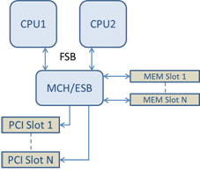
Shared Single Root PCI/Memory Architecture
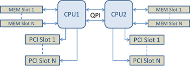
Distributed Multi-Root PCI/Memory Architecture
Example 4:
If the number of available NUMA node CPUs is not sufficient for queue allocation, what happens? If your platform has a processor that does not support an even power of 2 CPUs (for example, it supports 6 cores) then during queue allocation if SW runs out of CPUs on one socket it will by default reduce the number of queues to a power of 2 until allocation is achieved.
For example, if there is a 6 core processor being used, the SW will only allocate 4 FCoE queues if there only a single NUMA node. If there are multiple NUMA nodes, the user has the option to change NUMA node count to be >= 2 in order to have all 8 queues created.
Determining Active Queue Location
The user of these performance options will want to determine the affinity of FCoE queues to CPUs in order to verify their actual effect on queue allocation. This is fairly easy to do by using a fairly heavy small packet workload and an I/O application such as IoMeter: by monitoring the per-CPU CPU utilization using the built-in performance monitor provided by the OS, the CPUs that are supporting the queue activity should stand out. Again, they should be the first non-hyper thread CPUs available on the processor unless you have specifically directed allocation to be shifted via the performance options discussed above.
To make the locality of the FCoE queues even more obvious, you can also experiment with assigning the application affinity to an isolated set of CPUs on the same or another processor socket. For example, you could set the IoMeter application to run only on a finite number of hyperthread CPUs on any processor. Or if you have used the performance options to direct that queues be allocated on a specific NUMA node, you could set application affinity to a different NUMA node. The FCoE queues should not move and the activity should remain on those CPUs even though the application CPU activity moves to the other processor CPUs selected.